safe travels?
A mobility device is equivalent to a walking person’s legs, without which an individual with a mobility impairment would be unable to move. Arriving at a destination to find that one’s legs didn’t make it is a serious problem for anyone! But a lack of mobility is not the only issue. Without a customized seating system, many people with mobility impairments face the grave danger of pressure sores, which can result in severe injury and death.
Therefore, the utmost care and protection is required to ensure safety for mobility devices on aircraft and for those who use them. Since most carrier agents at airports are not experts on any given passenger’s mobility device, it is essential to provide clear instructions to those who handle these medical devices in order to ensure proper transport.
air travel configuration
The RESNA AT-1 Section 4 Standard provides design and labelling specifications for mobility devices designed for air travel. Whether or not an existing device meets the requirements of the Standard, it is necessary to configure the device for air travel for successful transport. The Standard also requires manufacturers to provide an air travel configuration card with each mobility device designed for air travel. The card is to provide the necessary information and steps required for preparing the mobility device in its air travel configuration. This card can and should also be used for existing devices to ensure safe handling and transport of the mobility device.
manual wheelchairs
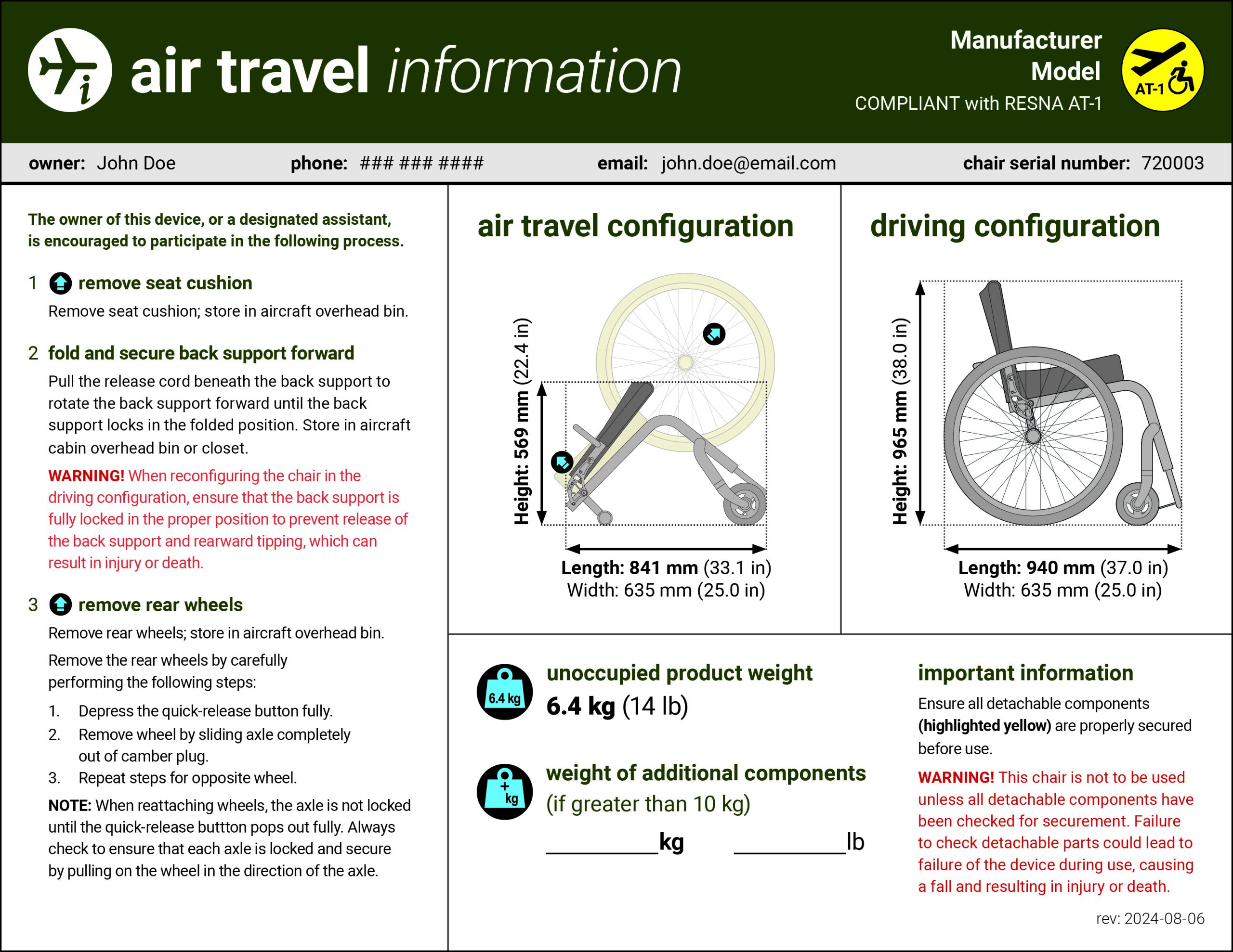
Manual wheelchairs can be reduced in size and stowed inside the passenger cabin in the priority space provided on airplanes with 100 seats or more. Otherwise manual wheelchairs may be stowed in the cargo area after necessary components have been removed. In both situations, the procedure for preparing the chair for air travel should be documented and attached to the device using an air travel configuration card.
powered mobility devices
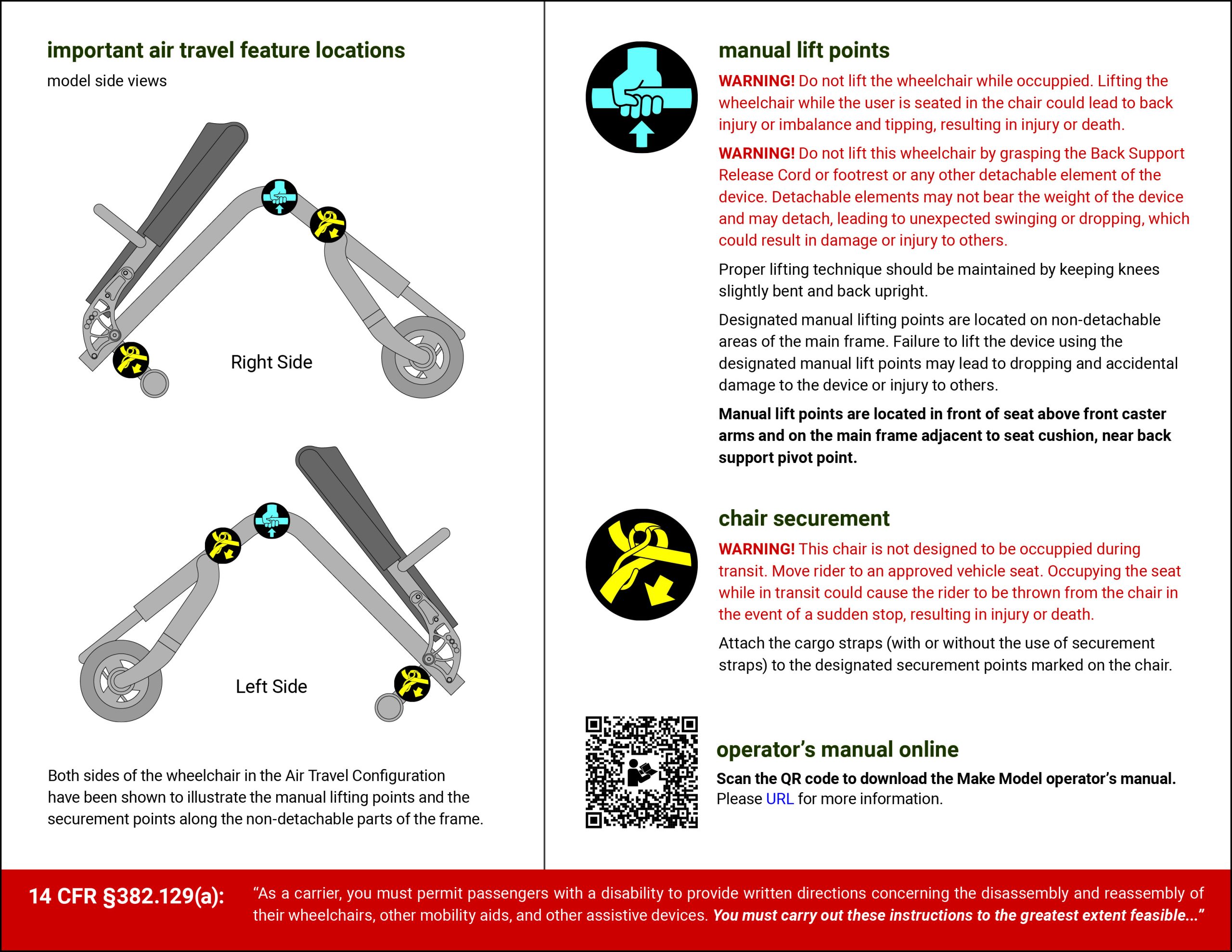
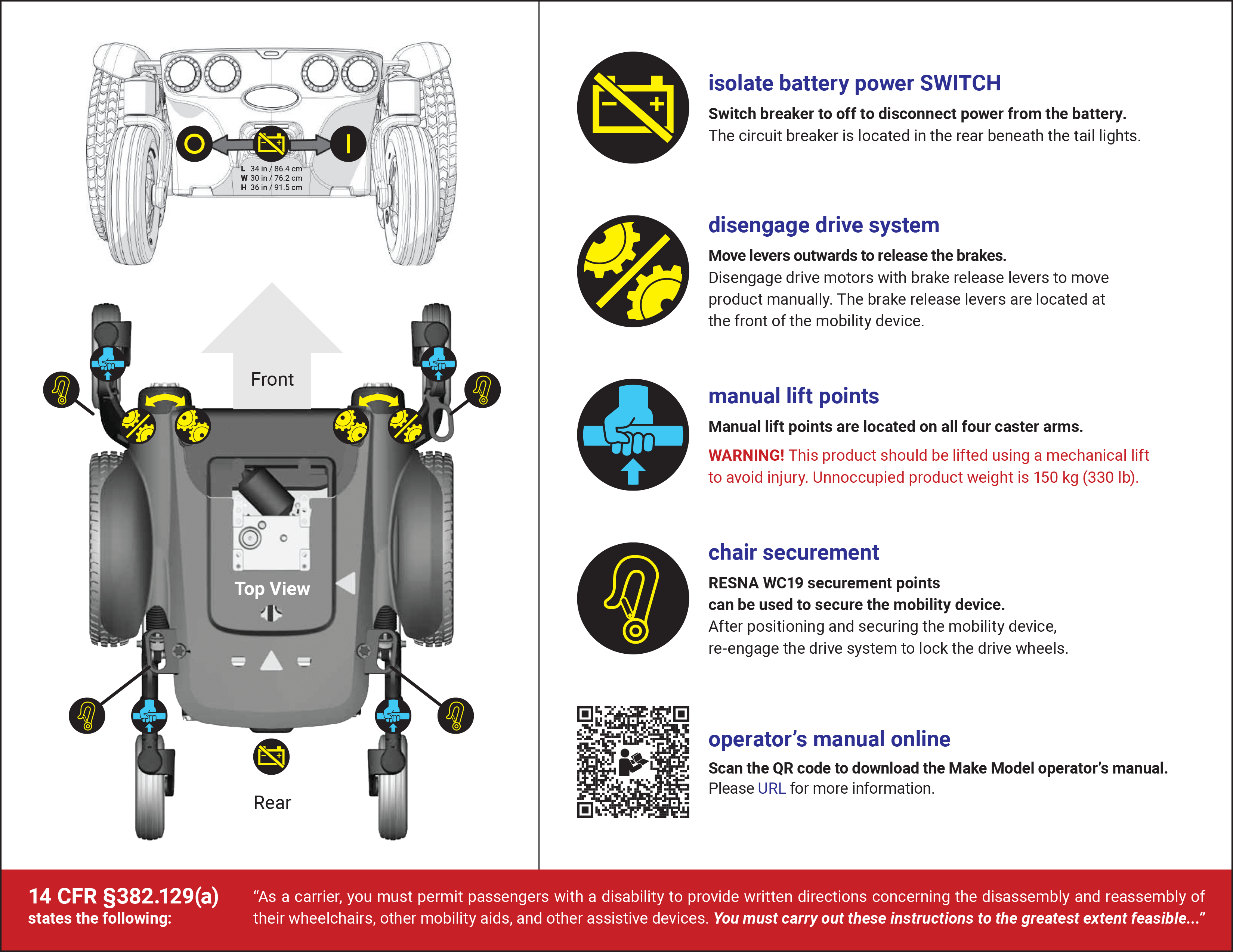
Powered mobility devices configured for air travel require a more thorough procedure than manual wheelchairs. It is important to label and locate all removable parts, battery location, battery isolation location, drive engagement and disengagement locations, manual lifting points, and securement points.
After all necessary components have been removed from the powered mobility device and the size of the device has been adequately reduced, the power must be disconnected. The AT-1 Section 4 Standard requires a battery isolation switch to be provided on the mobility device in order to easily disconnect the power. However, if an existing device does not have a battery isolation switch, the battery connection can be separated at the location of the batteries.
Next, the drive system must be disengaged in order to allow the device to be manually pushed, just like an automobile shifted to neutral. This will allow the air carriers to maneuver the powered mobility device whether or not the joystick has been removed.
Once positioned inside the cargo area at the desired location, the drive system must be re-engaged to prevent unwanted movement during air travel. The device must then be fastened in place at the proper securement points using securement straps, rather than simply relying on the brakes or storing luggage around and on top of the device.
Upon arrival, these steps must be performed in reverse so that the device will be safely returned to the user without any damage or change.
Leaving all these steps up to the carrier agents to figure out on their own is a recipe for disaster!
air travel configuration card
A reduction in damage to mobility devices transported for air travel is critical for the safety of passengers and will encourage people with mobility impairments to fly. One critical step in this goal is the development of an air travel configuration card for every mobility device that will be transported on an aircraft. Please see the sample card below to see information that must be disclosed to carrier agents handling mobility devices.
make your own
The following forms may be downloaded and used to help begin creating your own ATCC. The “ATCC Starter” form guides users through all the necessary items that must be provided in the air travel configuration card according to the RESNA AT-1 Section 4 Standard. The “Fillable ATCC” forms are fillable air travel configuration card PDF forms that may be used to create an air travel configuration card. In order to use a “Fillable ATCC” form, you will need download the file and complete the form using Adobe Acrobat. Please email us at mail@beneficialdesigns.com for any questions. Thank you.
instructions
Follow the instructions below to complete your air travel configuration card fillable form. Additional instructions are available from Adobe (see “Fill in PDF forms” instructions).
Tip: When using Adobe Acrobat, press Ctrl + E to open the text formatting options, which are available for certain fields.
- Click on one of the buttons below to open the PDF file in your web browser.
- Click the download or save button to save the file to your device.
- Photograph your mobility device according to instructions below.
- Save air travel symbols and place in photos as stickers in appropriate locations (optional).
To obtain air travel symbols to use in your air travel configuration card photos, please visit our symbols page. Scroll down to the air travel symbols section and right-click or tap and hold any symbols desired. Save the images to your device and use as stickers on your mobility device photos to identify any important locations.
Apple and Samsung devices provide built-in options for placing an image as a sticker onto a photo. Other third-party apps can also be used to edit the photos and add stickers.
- Open the PDF file and fill the form with the appropriate information.
- Press Ctrl + E to adjust text formatting where possible.
- Save the completed form.
- Print the completed form.
- Laminate and attach to your device.
The air travel configuration card should be laminated or printed on a durable material that will be able to withstand travel and weather. The card should be attached to the device in a location that is visible and noticeable to all air carrier agents.
It is recommended to print and carry spare copies of your air travel configuration card.
sample cards
front side sample (powered)

back side sample (powered)
front side sample (manual)
back side sample (manual)